 |  |  |
|---|---|---|
 |
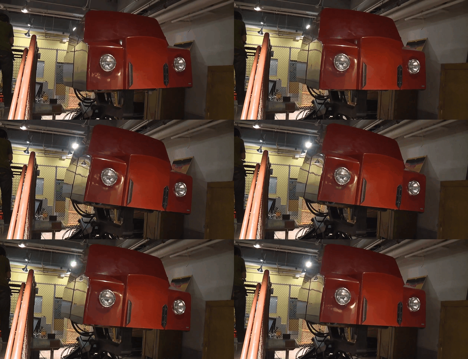
The Drexel Voyager is a 3 degree of freedom motion simulator manufactured by ETC and later donated to Drexel University. This project delivered an altered design (current design seen in the GIF below) more advanced in terms of technology and amenities. The new design can be seen in the image viewer on the left.
Mechanical verification and analyses were done using ANSYS 16.2. Those included Static Structural and Modal and can be seen on the image viewer at the bottom.

 |  |
|---|---|
 |
Drexel Voyager
The process of designing the modular deck included meeting the following requirements:
1. Easy manufacturability
2. Modular
3. Lightweight
4. Ability to hold more than 2 passengers
5. Low cost
Our thinking process took the project from different beam networks. To include modularity, we pin pointed rail systems. T-slotted and V-slotted rail systems were researched and the T-slotted 80/20 rails were decided to be meet three of our requirements, modularity, lightweightedness and low cost.
Before any brainstorming and concept designs, interviews were conducted with students and faculty members who had previously worked with the motino base. The interviews provided us with needs of the users which helped create a standard performance that the new design will be able to acheive. The resultant needs were quantified.
Values such as weight, motion envelope and dimensions helped us with visualising a new and improved design to accomodate all requirements. Next, we wanted to know how fast the actuators can move the motion base. We knew that this will determine the kind of dynamic loads present. The following pictures show the results of the accelerometer tests conducted using standard ASTM F2137 - 15a.

This helped us understand the accelerations that the structure will encounter. With some calculations, I determined the forces due to the acceleration of each of the actuators.
Knowing the requirements of the design, concepts were brainstormed. In addition to the standard use of the motion base, the design was to tend to use of the Drexel FSAE and the Drexel Theme Park Engineering and Design organizations. Having three sets of requirements in mind, we set forth to selecting the optimum concept.
Knowing our parameters and constraints, we selected T-slotted 80/20 rails to create a flat rectangular deck. This selection provides unlimited fastening positions and relatively simple assembly. Keeping in mind that this will be constructed by a set of students, the 80/20 was a great component.
Scrap writing was a big component of the brainstorming sessions we had. We listed the components that the whole deck will need to hold. This included seats, televisions, speakers, doors and such. Listing majority of the components resulted in an overwhelming realization. This project was more massive than expected. Hence, we scouted for volunteers and delegated responsibilities.
Using the list we made, we created a design concept consisting of interconnected 80/20 panels, creating fastening points for most of the components in the list. In the figure below, an AutoCAD rendered 2D top view of the deck can be seen. Two rows of seats were created occupying two seats each. Each of row has a flat surface for passengers to enter and exit. Space was also created for the TV mount at the front.

A Gantt chart was created and was followed all along the project. The project sustained for three quarters (9 months), with weekly reports and quarter end reports and presentations.

Using the force values and weights of individual components we compiled, I created a 3D model of the deck using Weldments function in SolidWorks. This was imported into ANSYS for the structural analysis. I introduced teh strucutre to lodas due to four passenger seats and a television module. Them being the heaviest of the components, were included in the analysis. A advising member of the Mechanical Engineering and Mechanics faculty informed us about calculating the natural frequency of the system. This analysis, we were told, would be a pleasant surprise for the faculty judging our project.
As can be seen below, Modal analysis was done in ANSYS in six differrent mode shapes. This is essential for manufacturing and usability purposes, as the strucutre cannot be subject to cyclic loading or vibrating bodies vibrating at the natural frequency of the strucutre.
 |  |  |
|---|---|---|
 |  |  |
